|
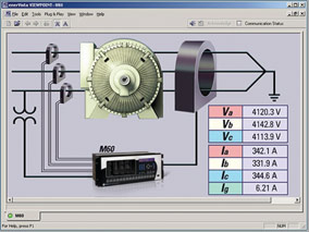
Plug-and-Play Motor Monitoring
Use Viewpoint Monitoring to Monitor Motor Protection Equipment
Monitor critical information such as:
- Number of motor starts
- Learned motor starting current
- Motor running hours
- History of motor trips
- Real time power quantities (amps, motor load)
- Motor temperature
|
|
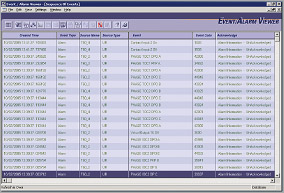
 View motor status using digital inputs, analog inputs and RTD inputs. View motor status using digital inputs, analog inputs and RTD inputs. |
| |
|
|
Supported Devices:
| M60 Motor Protection System |
239 Motor Protection System |
| 859 Motor Protection System |
MM200/MM300 Motor Management System |
| 869 Motor Protection System |
MM2/MM3 Intelligent MCC Controller |
| 469 Motor Protection System |
SPM Synchronous Motor Protection System |
| 369 Motor Protection System |
RRTD Remote RTD Module |
| 269 Motor Protection System |
|
|
|
| |
|
|
|
Plug-and-Play Transformer Monitoring
Use Viewpoint Monitoring to Monitor Transformer Protection Equipment
Monitor critical information such as:
- Transformer energization status
- Real time power quantities (amps, transformer loading, demand)
- Current harmonic analysis
- Accumulated loss of life
- Tap changer position
- Hottest transformer winding temperature
|
|
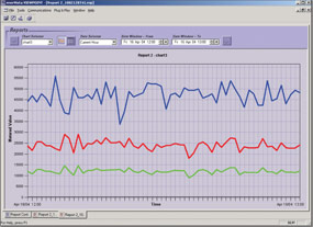
 Monitor total harmonic content in each phase for all
windings.
Monitor total harmonic content in each phase for all
windings.
|
| |
|
|
|
Supported Devices:
| T60 Transformer Protection System |
845 Transformer Protection System |
| T35 Transformer Protection System |
745 Transformer Protection System |
|
|
| |
|
|
|
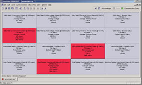
Plug-and-Play Generator Monitoring
Use Viewpoint Monitoring to Monitor Generator Protection Equipment
Monitor critical information such as:
- Generator loading
- Real time power quantities (amps, volts)
- Generator running hours
- Generator temperature
|
|
 Improve maintenance efficiency by analyzing trip operations. Improve maintenance efficiency by analyzing trip operations. |
| |
|
|
|
Supported Devices:
| G60 Generator Protection System |
889 Generator Protection System |
| G30 Transformer Generator System |
489 Generator Protection System |
|
|
| |
|
|
|
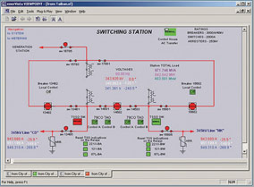
Plug-and-Play Feeder Monitoring
Use Viewpoint Monitoring to Monitor Feeder Protection Equipment
Monitor critical information such as:
- Breaker status
- Accumulated breaker arcing current
- Real time power quantities (amps, volts, demand, energy)
- Synchronism data
|
|
 Easily monitor synchronism levels needed for reclosing of circuit breakers. Easily monitor synchronism levels needed for reclosing of circuit breakers. |
| |
|
|
|
Supported Devices:
| 850 Feeder Protection System |
350 Feeder Protection System |
| F60 Feeder Protection System |
F35 Multiple Feeder Protection System |
| 750/760 Feeder Protection System |
F650 Feeder Protection System |
| 735/737 Feeder Protection System |
MIFII Feeder Protection System |
|
|
| |
|
|
|
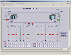
Plug-and-Play Breaker Monitoring
Use Viewpoint Monitoring to Monitor Breaker Equipment
Monitor critical information such as:
- Breaker status
- Number of breaker trip operations
- Real time current, voltage and power levels
|
|
 Monitor breaker equipment with predefined screens.
|
| |
|
|
|
Supported Devices:
| MVT MicroVersa Trip Unit |
EMVT Enhanced Microversa Trip Unit |
| GTU EntelliGuard TU Trip Unit |
Entellisys Low-Voltage Switchgear |
|
|
| |
|
|
|
Plug-and-Play Power Quality Monitoring
Use Viewpoint Monitoring to Monitor Power Quality Equipment and Measure Usage
Monitor critical information such as:
- Power quality and equipment status
- Load unbalances using real time and maximum and minimum values
- Consumption and cost of energy using inputs from revenue meters
- Amount of total harmonic distortion on the power system
|
|
 Monitor the power quality status for critical devices.
|
| |
|
|
|
Supported Devices:
| PQM / PQM II Power Quality Meter |
EPM 7000/7000P/7100 Electronic Power Meter |
| EPM 2000/2200 Electronic Power Meter |
EPM 9450/9650/9700 Electronic Power Meter |
| EPM 4600 Electronic Power Meter |
EPM 9800 Electronic Power Meter |
| EPM 5200/5300/5350 Electronic Power Meter |
EPM 9900/9900P Electronic Power Meter |
| EPM 6000/6100 Electronic Power Meter |
|
|
|
| |
|
|
|
Plug-and-Play Backup Power Monitoring
Use Viewpoint Monitoring to Monitor Critical Backup Assets
Monitor critical information such as:
- Availability of normal and emergency power sources
- Status of power source connections
- Real time voltages and frequency
- Switch status, timer settings and control switch position
- Stored events and exerciser schedules
|
|
 Monitor the status of critical backup assets.
|
| |
|
|
|
Supported Devices:
| MX150 Controller |
Lan Pro UPS |
| MX250 Controller |
SG-Series UPS |
| MX350 Controller |
|
|
|