


|
EnerVista Viewpoint Engineer - Legacy
Logic, IEC 61850 System Configuration and Real-Time Monitoring
Manufacturing for this product has been discontinued. Please contact us to discuss alternatives. Key Benefits
Key Features
|
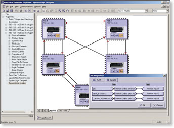
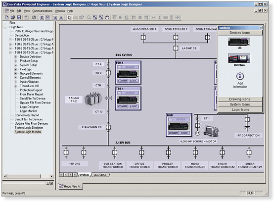
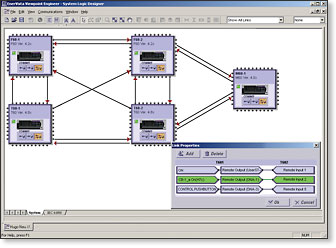
Design Control Logic at a System or Substation Level
The System Designer allows you to inter-connect the control logic distributed across multiple UR and URPlus devices by programming Remote I/O messages in an intuitive, graphical drag-&-drop environment.
|
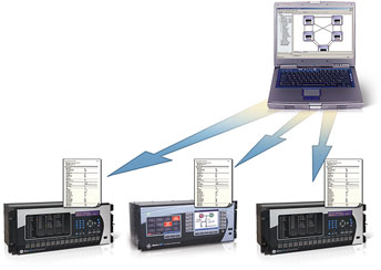
System Level Settings Configuration
Multiple Setting Files Created
|
 |
|
Configure Remote I/O communications for multiple relays in one easy drag-&-drop step |
|
|
Connectivity Report The connectivity report provides a detailed report of all peer-to-peer mappings between the settings files associated with a project, including:
The report will be generated as a PDF for simple archiving and emailing. A separate PDF report will be generated for each UR or URPlus device Document System Level Setting Diagrams
|
 |
|
Viewpoint Engineer will create a separate setting file for each UR or URPlus device that is configured in the System Designer. These setting files will contain all communication settings needed for Remote I/O |
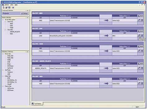
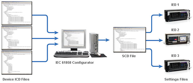
EC61850 Configurator
Import ICD and Generate SCD files using a single application
The IEC61850 enables system level configuration of the communications between all IEC61850 devices.
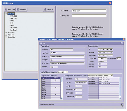
Importing ICD Files
Import ICD files from any IEC61850 Compliant device
Create SCD Files
Asset Manager
Manage all Assets in Your Substation or Power System
The Asset Manager will provide you with a tool to archive and manage critical information about any asset in your substation. All information in your power system can be stored in a Project Folder that can be shared between engineers and act as a single repository for any information required for your installed equipment.
Central Link to all Critical Information
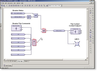
Graphical FlexLogic™ Designer
Simplify the process of creating complex control logic for substation automation in your UR, URPlus, and MM300 relays to perform functions such as advanced tripping, reclosing, interlocking, and transfer schemes.
|
Simplified Control Logic Creation
Documentation of Settings
Powerful Intuitive Compiler
|
|
| Design and document relay control logic in an intuitive drag-and-drop interface |
|
|
Logic Analyzer Real-Time Feedback of FlexLogic™ Status When connected to your UR, URPlus, and MM300 relays, Viewpoint Engineer will provide real-time feedback of the status of the FlexLogic™ inputs, logic gates, timers, latches and outputs for every equation in the relay. Simplified Troubleshooting
|
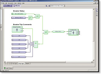 |
Relay internal logic represented visually to simplify commissioning and troubleshooting |
|
|
Real-Time Feedback of Peer-to-Peer Message Status Connecting Viewpoint Engineer to the local area network allows you to receive real-time feedback of the status of Remote I/O messages from both the relay sending the message and the relay receiving the Remote I/O message. Simplified System Troubleshooting
|
 |
|
Analyze the status of Remote I/O messages from both the Sending and Receiving devices in real-time |

