|
Multilin 750/760 - Legacy
Feeder Protection System
Manufacturing for 750/760 has been discontinued. As an alternative, please refer to the 850. The 750/760 Feeder Protection System, a member of the SR Family of protection relays, with draw out capability intended for primary protection and management of distribution feeders. The 750/760 has specific features for industrial environments, including a drawout case to limit downtime during maintenance and conformal coating for harsh environments.
|
Key Features | |
|
|
Protection and Control
The 750/760 Feeder Protection System is a digital relay intended for the management and primary protection and control of distribution feeders. This easy to use relay provides comprehensive protection functions for feeders and back up protection for bus, transformers and transmission lines at a reduced product life cycle cost.
EnerVista Software
The EnerVista™ Suite is an industry-leading set of software programs that simplifies every aspect of using the 750/760 relay. The EnerVista™ suite provides all the tools to monitor the status of your protected asset, maintain the relay, and integrate information measured by the 750 into DCS or SCADA monitoring systems. Convenient COMTRADE and Sequence of Events viewers are an integral part of the 750 Setup software included with every 750 relay, to carry out postmortem event analysis to ensure proper protection system operation. Learn More
Key Features
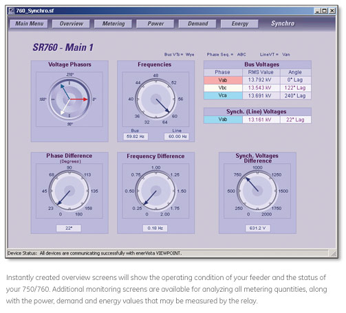
Monitoring and Metering
The 750/760 features advanced monitoring and metering functions which include:
Fault Locator
The relay uses captured data to calculate the type, distance to and the impedance of the fault. Records of the last 10 faults are stored.
Breaker Conditions
The relay calculates the per-phase wear on the breaker contacts to establish a threshold. When the breaker maintenance threshold is exceeded the relay can trigger an alarm. An alarm is also generated if the relay detects that the supervisory trickle current is not present. A failure to respond to an open or close signal in a programmed time can be used to generate an alarm.
VT Failure
The VT failure feature monitors each phase of input voltage, generating an alarm and sending the programmed output signals when a failure is detected.
Analog Inputs
Any external quantity may be monitored via an auxiliary current input. Two analog input level monitoring elements and two rate-of-change elements are available. When the measured quantity exceeds the pickup level, the relay can trigger an alarm or signal an output.
Event Recording
The relay captures and stores the last 512 events, recording the time, date, cause, and system parameters. Events may be recorded selectively by category, so that only events of interest are recorded.
Oscillography
A block of configurable volatile memory can be used for recording samples of the AC input voltages and current, and the status of logic inputs and output relays. This memory can be configured between the ranges of two to 16 blocks with 16 to 256 power frequency cycles of data respectively. The amount of pre-event data recorded is set by the user. Trace memory recording can be triggered by operation of selected features or logic inputs.
Trip Counter
The number of breaker trip operations is recorded, and can be displayed for statistical purposes (useful for units without operation counters).
Key Features
Advanced Communications
The 750/760 is equipped with three standard serial communications ports, one RS232 located in the front panel, and two RS485/RS422 in the rear of the relay. A rear Ethernet port is also available as an optional feature. The front panel port allows easy local computer access. The rear ports provide remote communications or connection to a DCS, SCADA, or PLC. The baud rate of all the serial ports is variable from 300 to 19,200 bps. The optional Ethernet port can be used to connect the 750/760 to 10 Mbps Ethernet networks. The 750/760 supports ModBus® RTU, DNP3.0 Level 2, and ModBus® RTU TCP/IP protocols.
The three serial ports support ModBus® RTU protocol, while any one of the two rear ports but not both can be configured to support DNP 3.0 Level 2. The optional Ethernet port supports ModBus® RTU via TCP/IP protocol. The communication system of the 750/760 is designed to allow simultaneous communication via all ports.
Using Ethernet as the physical media to integrate the 750/760 to Local or Wide Area Networks, replaces a multipoint wired network (e.g., serial Modbus®), and eliminates expensive leased or dial-up connections, reducing monthly operating costs.
User Interface
Various user interfaces facilitate operation of the 750.
Display
A 40 character display allows access to setpoints, actual values, and diagnostic messages generated by a trip or alarm condition. The 750 can display 30 user-selected messages during keypad inactivity.
Indicators
Twenty LEDs indicate relay status, system status, and trip and alarm conditions.
IRIG-B Input
This feature provides time synchronization via standard GPS clock inputs.
EnerVista Software
The EnerVista™ Suite is an industry-leading set of software programs that simplifies every aspect of using the 750/760 relay. The EnerVista™ suite provides all the tools to monitor the status of your protected asset, maintain the relay, and integrate information measured by the 750 into DCS or SCADA monitoring systems. Convenient COMTRADE and Sequence of Events viewers are an integral part of the 750 Setup software included with every 750 relay, to carry out postmortem event analysis to ensure proper protection system operation. Learn More
Retrofit Kit

Explore the 8 Series Retrofit Kit
Retrofit Existing SR 750 Devices to the Multilin 850 in Minutes
Traditionally, retrofitting an existing relay has been a challenging, time consuming task often requiring re-engineering, new drawings, panel modifications, re-wiring and re-testing.
The 8 Series Retrofit Kit provides a quick, 3-step solution to upgrade previously installed SR 735 or SR 750/760 Devices. With the new 8 Series Retrofit Kit users are able to install the 850 Feeder Management System without modifying existing cutouts and wiring, and without any drawing changes or re-engineering time.
Buy 750/760 to 850 Retrofit Kit
Easy 3-Step Process to Upgrade in as Fast as 21 Minutes

EnerVista 8 Series Setup Software provides automated setting file conversion. Once completed, a graphical report is provided to verify and call out any specific settings that may need attention. |

Simply remove the terminal blocks and then remove the SR chassis from the panel. No need to disconnect any of the field wiring. |

Insert the new 8 Series Retrofit chassis into the switchgear and simply plug-in the old terminal blocks - there is no need to make any cut-out modifications or push and pull cables. |