


|
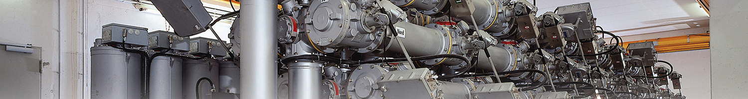
F35gSF6-free g3-Gas-Insulated Substations up to 145 kVGE's F35g is a g3-gas-insulated substation up to 145 kV, up to 3,150 A and 40 kA using GE’s revolutionary g3 gas mixture as an insulating and switching alternative to SF6. The F35g g3-GIS is designed to deliver the same performances and reliability features as today’s existing SF6 switchgear, without SF6's environmental impacts. Compared to SF6 switchgear, they feature:
Key Characteristics
The F35 is a compact and accessible GIS solution, with a bay footprint below the market average. Up to 2 bays are assembled together, wired, tested and shipped enabling shorter site works. GE’s F35g is the first SF6-free g3-gas-insulated substation up to 145 kV to complete ENA assessment in the UK. |
| General ratings | |
| Reference electrotechnical standards | IEC |
| Voltages | Up to 145 kV |
| Insulating and switching medium | g3 gas mixture |
| Withstand voltages | |
| Short-duration power-frequency, phase-to-earth / across isolating distance | 275/315 kV |
| Lightning impulse, phase-to-earth / across isolating distance | 650/750 kVp |
| Frequency | 50 Hz |
| Continuous current | up to 3150 A |
| Short-time withstand current | 40 kA |
| Peak withstand current | 108 kAp |
| Duration of short-circuit | 3s |
| Circuit-breaker ratings | |
| First-pole-to-clear factor | 1.5 |
| Short-circuit breaking current | 40 kA |
| Short-circuit making current | 108 kAp |
| Operating sequence | O-0.3s-CO-3 min-CO CO-15s-CO |
| Drive type (three-phase or single-phase) | Pure-spring |
| Breaking time | 50ms |
| Closing time | 95ms |
| Mechanical endurance | M2 class |
| Capacitive switching | C2 class |
| Disconnector and low-speed earthing switch ratings | |
| Capacitive current switching | 0.1 A |
| Bus-transfer current switching capability | 2520/20 A / V |
| Mechanical endurance | M2 class |
| Make-proof earthing switch ratings | |
| Making current capability | 108 kAp |
| Switching capability - electromagnetic coupling | 80/2 A / kV |
| Switching capability - electrostatic coupling | 2/6 A / kV |
| Mechanical endurance | M1 class |


