


|
MiCOM Agile P54A, P54B, P54C & P54E
Multi-ended Line Differential Protection Systems
The MiCOM P54A/B/C/E range is designed for overhead line and cable applications up to 6 terminals, interfacing readily with the longitudinal (end-to-end) communications channel between line terminals. Previously, transmission and distribution circuits would have two or three ends only, whereas five or more ends are becoming common to connect renewable generation. All models are ready for protection topologies ranging from two to six terminals, whether those multi-terminals exist now, or are provisioned for connection in the future. Multi-ended current differential protection uses a high-speed and innovative biased differential characteristic. Phase-segregated differential elements provide consistent detection of solid and resistive faults. Key features:
Application: Adapted to suit many different substation and protected feeder topologies:
|
What's New
Protect lines with up to 6 terminals
For more than 100 years, electric power plants have mainly been large, utility-owned facilities, feeding distributed load based on unidirectional power flow. Over the past 20 years, smaller, independent power generation plants have been developed and distributed within electrical networks. The increasing number of Distributed Generation (DG) sites, and their increasing power ratings from kW to hundreds of MW, create new challenges for network planning and operation.
Distributed Generation Tee Infeeds to Existing Transmission Lines
Circuits near the coast may be candidates for tee infeeds to evacuate renewable energy from onshore and offshore wind generation. A tee infeed to a nearby transmission line can be a more cost effective solution to connect the generation to the grid than building a new substation. This economy enables more Distributed Generation connections to penetrate the network helping to meet green energy connection targets and reduce greenhouse gas emissions.
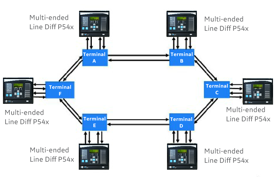
Multi-Ended Circuit Differential Lines
Previously transmission and distribution circuits would have two or three ends only. However, five or more ends are becoming common because large Distributed Generation sites such as onshore or offshore windfarms and solar farms are being connected to the grid. As the power networks evolve to transport power in ever more complex ring and meshed networks, line/cable differential protection becomes increasingly attractive, with its inherent ability to address grading/selectivity challenges and is scalable for multi-terminal circuits able to accommodate many connections of distributed generation along the line. GE Grid Solutions’ multi-ended current differential protection is now ready for any protection topology from two to six terminals, whether those multi-terminals exist now, or are provisioned for connection in the future.
Functional Block Diagram
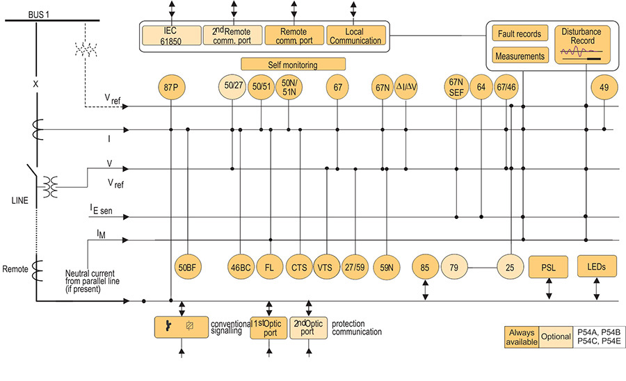
ANSI ® Device Numbers and Functions
|
|
|
Key Features
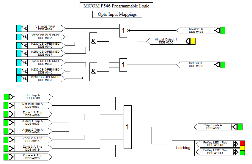
Programmable Scheme Logic
Powerful graphical logic allows the user to customise the protection and control functions. The logic includes 32 timers, gates (OR, AND, MAJORITY) and set/reset latch functions, with the ability to invert the inputs and outputs and provide feedback.
The system is optimised to ensure that the protection outputs are not delayed by PSL operation. The programmable scheme logic is configured using the graphical S1 Agile software. The relay outputs may be configured as latching (lockout) or self-reset. All aspects of MiCOM P40 IED configuration are managed using the S1 Agile software.
Measurement and Recording Facilities
All events, fault and disturbance records are time tagged to a resolution of 1 ms. An optional IRIG-B port is available for accurate time synchronisation.
Power System Measurements
Instantaneous and time integrated voltage, current and power measurements are provided. These may be viewed in primary, or secondary values.
Fault Location
A fault location algorithm provides distance to fault in miles, kilometres, ohms or percentage of the line length. The proven algorithm employed tolerates pre-fault loading and fault arc resistance.
Event Records
Up to 1024 time-tagged event records can be stored. An optional modulated or demodulated IRIG-B port is available for accurate time synchronisation.
fault Records
The last 15 fault records are stored.
Disturbance Records
The oscillography has 16 analogue channels, 64 digital and 1 time channel, all at a resolution of 48 samples/cycle.
Key Features
Protection Communications Interfacing
To ensure compatibility with standard communications equipment, the MiCOM P54x Agile multi-ended line differential series is designed to work with IEEE C37.94TM. A direct fibre optic connection to a MUX is possible if the MUX is IEEE C37.94TM compliant.
In direct fibre optic applications, 1300 nm and 1550 nm channel options are available. The transmitters are designed with a large "optical budget" to support up to 150 km.
Communications Supervision
Dependable communications are essential for high-performance differential protection. Each active longitudinal channel is independently monitored and reports error statistics in line with guidance from ITU-T G.821.
Multi-ended line differential works in a ring connection, which provide comms redundancy. In the event of degraded communications, the ring communications channels will continue to provide protection, thus providing duplicated links via diverse communications paths.
Alternatively, back-up overcurrent elements can be switched into service, either as permanent parallel main protection, or temporary protection only during channel outages.
Communications with Remote Operators and Substation Automation
Rear Scada Communication
The wide range of communications options, including IEC 61850, provides interfacing with almost any type of substation automation system or SCADA system.
The following protocols are available:
P54x devices can be enhanced with an optional redundant Ethernet board. The redundancy is managed by the market's fastest recovery time protocols: IEC 62439-3 PRP and HSR allowing bumpless redundancy and RSTP, offering multi-vendor interoperability. The redundant Ethernet board supports either modulated or demodulated IRIG-B and the SNTP protocol for time synchronisation. The redundant Ethernet board also has a watchdog relay contact to alarm in case of a failure.
Second Rear Courier Port
An additional second rear port can be ordered as an option, designed typically for dial-up modem access by protection engineers/operators when the main port is reserved for SCADA traffic. This port also offers the option of -103 communications when IEC 61850 is the chosen first port protocol.
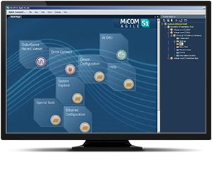
MiCOM S1 Agile
Key benefits:
Engineering Tool Suite
S1 Agile is the truly universal PC tool for MiCOM Agile relay, assemble all tools in a palette for simple entry, with intuitive navigation via fewer mouse-clicks. No-longer are separate tools required for redundant Ethernet configuration, phasor measurement unit commissioning, busbar scheme operational dashboards, programmable curve profiles or automatic disturbance record extraction – applications are embedded. MiCOM S1 Agile supports all existing MiCOM, K-Series and Modulex, including a utility for automatic conversion of setting files from previous generations of numerical relays like K-series and MiCOM P20 to the latest P40 Agile models.
To move to the future, with no loss of functionality, no loss of device support, and full compatibility with your installed base and system architecture – request a copy of S1 Agile with the contact form link below.
Key features in the MiCOM S1 family:
MiCOM S1 Agile software request
To receive the MiCOM S1 Agile, please use our Contact form. This will also ensure that you are kept up-to-date with the latest enhancements, including updates and bug fixes.
Models
 |
P54A compact (40TE), economical line differential protection without VT inputs, offering non-directional backup protection. |
|
P54B compact (40TE), economical line differential protection with directionalised back-up protection and inbuilt reclosing and check synchronism. |
 |
P54C transmission-class 1/3-pole tripping line differential protection with backup protection and inbuilt reclosing and check synchronism (built from today’s P543 hardware). |
 |
P54E transmission-class 1/3-pole tripping line differential protection with back-up protection and inbuilt reclosing and check synchronism with a large number of binary I/O for traditional hardwired schemes (built from P545 hardware). |

