Explore GE Vernova
Resource Library
Get access to curated content, tools, and useful resources to help you face all your grid challenges.
Access the library
Electrification Businesses
Electrification Software
Power Conversion
Solar & Storage Solutions
Category banner
Banner image
Protection Relays
Generator Protection

Home > Grid Automation > Protection Relays > Generator Protection > P34x

Product Lookup
Protection & Control Online Store (new window)
Protection & Control Support
Event Calendar
Protection & Control Press Room
Related Links
  Interactive Selector Guide
  Spotlight Application
  Typical Applications
  Generator Principles & Protection
  GSA Schedule
  Industrial Energy Management Systems
  Legacy Generator Protection

MiCOM Agile P34x
Generator Protection Systems

GE's MiCOM Agile P34x generator protection relays provide flexible and reliable integration of protection, control, monitoring and measurement functions for a wide range of applications. The P34x relay platform is available in six models that cover most installations from small generators to sophisticated systems including generator-transformer applications and large variable speed double fed induction pumped storage machines.

Key features:

  • Comprehensive protection functions, flexible communications options with a number of protocols and ports
  • Generator turbine abnormal frequency protection monitors the accumulated time spent at each frequency band
  • Check synchronization function with an option to compensate for magnitude and phase angle
  • User-friendly programmable scheme logic allows easy customization of the protection and control functions
  • Current loop analogue inputs and outputs for remote monitoring
  • No internal batteries in GE-branded models – removes a maintenance item and eases air-freight logistics
  • Binary inputs ESI48-4 EB2 compliant
  • Binary inputs offer programmable pickup voltage thresholds and filtering enabling a truly universal application
  • High break output contacts eliminate reliance on auxiliary devices
  • Unique low frequency protection for variable speed double fed induction machines
  • Rotor earth fault protection
  • Harsh environment protection extends the life of the product
What's New
Overview
Models
Software
Retrofit/Refurbish

What's New

MiCOM P40 Agile Explorer

The new software features:

  • Enhanced power protection with 4 stages of single phase power/VAR (P341-6) and 4 stages of 3 phase power/VAR protection (P341-6)
  • New minimum power setting reduced to 0.2%Pn for large generator reverse power applications
  • Independent voltage dependent overcurrent (51V) and underimpedance (21) protection
  • IEC 61850 Edition 2 support - with support for Ed 2 test modes for online testing.
  • IEEE 1588 Precision Time Protocol - efficient time synchronizing direct from the substation LAN.
  • Editable Logical Nodes/Devices - to customize the IEC 61850 modelling and maximize interoperability.
  • Role based access control (RBAC) for centralized authentication.
  • Authorization and account management via RADIUS, and directly on the relay.
  • Security Event Management via Syslog.
  • Duplicate GOOSE Rejection - Defense against incorrect publishing of out-of-sequence or duplicated GOOSE messages by other devices on the network.
  • SNMP version 2c and cybersecure v3 - network management tools can monitor protection IEDs.
  • New Ethernet Board - Improved traffic density handling, PRP, HSR and RSTP supported in the same order option for standardization.

Overview

GE's Agile P34x generator protection solutions provide extensive functionality to meet all generator and generator - transformer applications, including differential protection for fast and selective tripping of phase and earth faults. All generator protection, control, monitoring, recording and communications components are housed within one box, and the solutions are accompanied by a comprehensive library of hardware options, protection and control functions to meet system requirements.

Key benefits:

  • Extensive condition based monitoring features for generators and transformers
  • Graphical programmable scheme logic eases protection scheme creation and avoids the need for external logic controllers
  • Range of different protocols (MODBUS, DNP3, IEC 60870-5-103 and IEC 61850) are available
  • IEC 61850 / DNP3.0 redundant Ethernet, supporting self healing ring, RSTP, dual homing, PRP or HSR
  • Programmable curves for easy protection customization

Main characteristics:

  • Sensitive rotor earth fault protection using low frequency injection method
  • Harsh Environment Option to protect against corrosive gases such as H2S or SO2
  • Generator and transformer thermal overload, transformer loss of life and through fault monitoring
  • Extensive protection for large machines such as pole slipping and 100% stator earth fault protection (3rd harmonic and low frequency injection method)
Functionnal Block Diagram

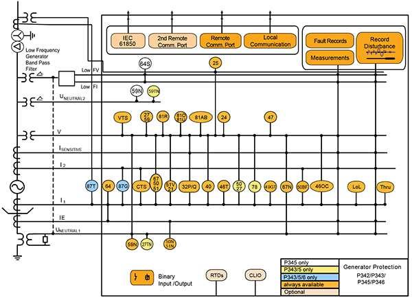
ANSI ® Device Numbers and Functions

Device Number Function
87GT Generator/transformer differential
50DT

Interturn (Split Phase)

50/51/67

Directional/non directional, instantaneous/time delayed phase overcurrent

50N/51N Non directionnal, instantaneous/time delayed phase earth fault
67N/67W

Sensitive directional ground fault / wattmetric ground fault

64 Restricted ground fault
51V Voltage dependent over current
21 Under impedance
59N

Neutral voltage displacement/residual overvoltage, interturn -measured,derived

27/59 Under/Over voltage
Device Number Function
81U/81O/81R Under/over frequency/rate of change of frequency
81AB Turbine abnormal frequency
32P/Q Forward/Reverse, under/over Power/Var
40 Loss of field
46T Negative phase sequence thermal
46OC Negative phase sequence overcurrent
47 Negative phase sequence overvoltage
49G/T Stator/Transformer thermal overload
24 Overfluxing
78 Pole slipping
27TN/59TN

100% stator ground fault (3rd harmonic neutral under/over voltage)

64S 100% Stator ground fault (low frequency injection) with GPM-S
Device Number Function
50/27 Unintentional energization at standstill
50BF CB Fail
25 Check synchronizing
64R Rotor ground fault (available with CLIO option and P391)
RTD RTD Measurement
CTS CT Supervision
VTS VT Supervision
PSL Programmable Logic
TCS Trip Circuit Supervision
Lol/Thru Loss of life/Thru fault monitor

Agile P34x Models

P342 Small Generator Management IED.

Manufacturing for P342 has been discontinued. As an alternative, please refer to 889.

P343 Medium to Large Sized Generator Management IED

P345 Large Generator Management IED with 100% Stator Earth Fault

P346 Small Generator Management IED with Differential

The P346 is under last-time buy. Orders may be placed until 15th June 2024 and will be fulfilled based upon availability. As an alternative, please refer to P343, 889, G60 or G30.

P348 Variable Speed Double Fed Induction Machine protection IED

Manufacturing for P348 has been discontinued. Please contact us to discuss alternatives.

P391 Rotor Earth Fault Unit

GPM-S 100% stator earth fault unit (20Hz injection), used with the P345

MiCOM S1 Agile

Key benefits:

  • Powerful, free of charge, PC toolsuite
  • Optimum management of the installed base, structured as per the substation topology
  • Intuitive and versatile interface with file management facilities
  • Logical structure based on substation, voltage level and bay
  • Version control and cross-checking facilities for IED settings
  • Real-time measurement visualization – MiCOM S1 Agile extends to all MiCOM Agile IEDs - including P847 PMU and busbar schemes

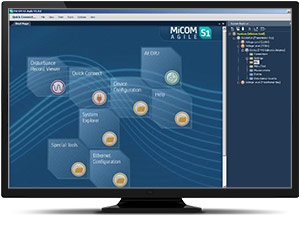
Engineering Tool Suite

S1 Agile is the truly universal PC tool for MiCOM Agile relay, assemble all tools in a palette for simple entry, with intuitive navigation via fewer mouse-clicks. No-longer are separate tools required for redundant Ethernet configuration, phasor measurement unit commissioning, busbar scheme operational dashboards, programmable curve profiles or automatic disturbance record extraction – applications are embedded. MiCOM S1 Agile supports all existing MiCOM, K-Series and Modulex, including a utility for automatic conversion of setting files from previous generations of numerical relays like K-series and MiCOM P20 to the latest P40 Agile models.

To move to the future, with no loss of functionality, no loss of device support, and full compatibility with your installed base and system architecture – request a copy of S1 Agile with the contact form link below.

MiCOM S1 Agile software

Key features in the MiCOM S1 family:

  • GE’s integrated engineering tool that provides users with access to automation IED configuration and record data
  • Integrated configuration and monitoring features
  • Send and extract setting files
  • Event and disturbance record extraction and analysis

MiCOM S1 Agile software request

To receive the MiCOM S1 Agile, please use our Contact form. This will also ensure that you are kept up-to-date with the latest enhancements, including updates and bug fixes.

Refurbishment Solutions

GE’s latest MiCOM P340 models offer a perfect functional match for LGPG relay from the heritage installed-base brands of GEC Measurements, GEC Alsthom, Alstom and Areva:

Refurbishment Solutions – “If It’s Blue Think to Renew”

GE’s latest MiCOM P340 series models P341 to P348 inclusive offer an ideal path to refurbish an older installed base of MiCOM P340 relays. Whether those older products were initially sold as Alstom or AREVA-branded products, newer models retain pin-pin refurbishment capability. Advantageously, users can benefit from the advancements made in protection, control, communications, hardware that have taken place in the intervening years. The new P40 retains form, fit and function compatibility but delivers the latest platform and software ready for today’s environment, and for future-proofed application for the decades ahead. Pin-Pin Upgrade Methodology:

  • Take the order code (CORTEC) of the older relay being removed, typically a blue case relay
  • Translate to today’s latest GE MiCOM model, adding Ethernet options if required
  • Order the new P40 relay
  • Extract settings and logic, use S1 Agile toolsuite to convert settings
  • Detach the terminal blocks from old relay, leaving wiring attached / detach terminal blocks from the new.
  • Carefully examine the terminal blocks to see that no physical damage has occurred since installation
  • Mount new relay. Old relay blocks fit straight onto the new relay - safer, less wiring to reconnect.
  • It is recommended to apply rated current and voltage to the relay CT/VT inputs during secondary injection testing to check the continuity of the CT/VT terminal block connections to the relay.
  • Download converted files
  • Test, return circuit to service with only minutes of downtime

Contact us for advice and support