Overview
- 4-stages of non-directional/directional overcurrent, earth fault, negative phase sequence overcurrent, sensitive earth fault protection
- 2-stage under/over voltage, 9-stage under/overfrequency, check synchronism, autoreclose and breaker fail
- IEC 61850 redundant Ethernet, with RSTP and IEC 62439 PRP and HSR – with HSR support for up to 50 nodes in a ring
- Graphical programmable scheme logic eases protection scheme creation and avoids the need for external logic controllers
- Hardware modularity extends up to a maximum of 48 binary (opto) inputs
- Integrated functionality permits control of up to eight switchgear elements in the bay, in addition to circuit breaker control
Key benefits:
- Comprehensive library of hardware options, protection and control functions suitable to meet your system requirements
- Advanced autoreclose and synchronizing options, including predictive closing such that CB primary contacts touch near to the exact moment that systems drift in-phase
- The standard and user-programmable curves, supplemented by load blinders and voltage supervision offer fast and dependable fault tripping, without constraining circuit loadability
- Distance to fault location assists dispatching of maintenance crews
Functional Block Diagram
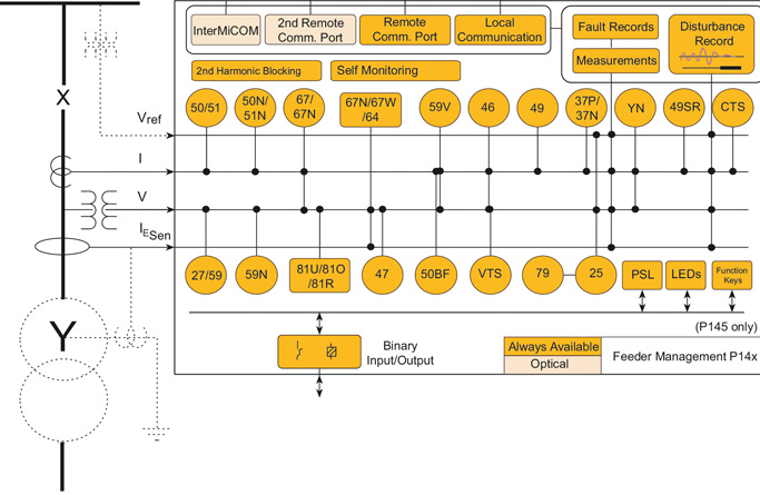
ANSI ® Device Numbers and Functions
| Device Number |
Function |
| 25 |
Check Synchronising |
| 27 |
Phase and Line Undervoltage |
| 32 |
Phase Directional Power |
| 37 |
Undercurrent |
| 46 |
Negative Sequence Overcurrent |
| 47 |
Negative Sequence Overvoltage |
| 49 |
Thermal Overload |
| 50/27 |
Switch-on to Fault |
| 50 |
Phase Definitive Time Overcurrent |
| 51 |
Phase Inverse-Time Overcurrent |
| 52 |
Breaker and Isolator Control |
| 59 |
Phase and Line Overvoltage |
| dv/dt |
Rate of Change of Voltage |
| 67 |
Directional Phase Overcurrent |
| 68 |
Inrush Blocking |
|
|
| Device Number |
Function |
| 79 |
Autoreclose |
| 85 |
InterMiCOM Teleprotection |
| 86 |
Latching/Lockout Contacts |
| 87 |
High-Impedance Busbar Differential |
| 21BL |
Load Encroachment/Blinder |
| 21FL |
Fault Locator |
| 32S |
Sensitive Power |
| 46BC |
Broken Conductor |
| 49SR |
Silicon Rectivier Thermal |
| 50BF |
CB Failure |
| 50N |
Earth Fault Definitive Time Overcurrent |
| 51N |
Neutral/Ground IDMT Overcurrent |
| SEF |
Sensitive Earth Fault, I cos and I sin |
| 51R |
Voltage Restrained Overcurrent |
| 51V |
Voltage Controlled Overcurrent |
|
|
| Device Number |
Function |
| PSL |
Programmable Logic |
| CLP |
Cold Load Pick Up |
| 59N |
Neutral Voltage Displacement |
| 59S |
Busbar Buswire Supervision |
| 64N |
Restricted Earth Fault |
| 67N |
Directional Neutral/Ground Overcurrent |
| 67W |
Wattmetric Earth Fault |
| 81df/dt |
Rate of Change Frequency |
| 81O |
Overfrequency |
| 81R |
Load Restoration |
| 81U |
Underfrequency |
| 81V |
Undervoltage Blocking |
| CTS |
CT Supervision |
| VTS |
VT Supervision |
| YN |
Neutral Admittance |
|
Agile P14x Models Available
- P141 Feeder management IED
- P142 Feeder management IED with autoreclose
- P143 Feeder management IED with autoreclose and synchronizing
- P144 Feeder management IED with transient earth fault detection for isolated/Petersen systems
The P144 is under last-time buy. Orders may be placed until 1st December 2024 and will be fulfilled based upon availability. As an alternative, please refer to P84.
- P145 Feeder management IED with autoreclose, synchronizing and function keys
MiCOM S1 Agile
Key benefits:
- Powerful, free of charge, PC toolsuite
- Optimum management of the installed base, structured as per the substation topology
- Intuitive and versatile interface with file management facilities
- Logical structure based on substation, voltage level and bay
- Version control and cross-checking facilities for IED settings
- Real-time measurement visualization – MiCOM S1 Agile extends to all MiCOM Agile IEDs - including P847 PMU and busbar schemes
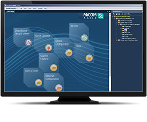
Engineering Tool Suite
S1 Agile is the truly universal PC tool for MiCOM Agile relay, assemble all tools in a palette for simple entry, with intuitive navigation via fewer mouse-clicks. No-longer are separate tools required for redundant Ethernet configuration, phasor measurement unit commissioning, busbar scheme operational dashboards, programmable curve profiles or automatic disturbance record extraction – applications are embedded. MiCOM S1 Agile supports all existing MiCOM, K-Series and Modulex, including a utility for automatic conversion of setting files from previous generations of numerical relays like K-series and MiCOM P20 to the latest P40 Agile models.
To move to the future, with no loss of functionality, no loss of device support, and full compatibility with your installed base and system architecture – request a copy of S1 Agile with the contact form link below.
Key features in the MiCOM S1 family:
- GE’s integrated engineering tool that provides users with access to automation IED configuration and record data
- Integrated configuration and monitoring features
- Send and extract setting files
- Event and disturbance record extraction and analysis
MiCOM S1 Agile software request
To receive the MiCOM S1 Agile, please use our Contact form. This will also ensure that you are kept up-to-date with the latest enhancements, including updates and bug fixes.
Refurbishment Solutions – “If It’s Blue Think to Renew”
GE’s latest MiCOM P140 series models P141 to P145 inclusive offer an ideal path to refurbish an older installed base of MiCOM P140 relays. Whether those older products were initially sold as Alstom or AREVA-branded products, newer models retain pin-pin refurbishment capability. Advantageously, users can benefit from the advancements made in protection, control, communications, hardware and cybersecurity that have taken place in the intervening years. The new P40 retains form, fit and function compatibility but delivers the latest platform and software ready for today’s environment, and for future-proofed application for the decades ahead.
Pin-Pin Upgrade Methodology:
-
Take the order code (CORTEC) of the older relay being removed, typically a blue case relay
- Translate to today’s latest GE MiCOM model, adding Ethernet options if required
- Order the new P40 relay
- Extract settings and logic, use S1 Agile toolsuite to convert settings
- Detach the terminal blocks from old relay, leaving wiring attached / detach terminal blocks from the new.
- Carefully examine the terminal blocks to see that no physical damage has occurred since installation
- Mount new relay. Old relay blocks fit straight onto the new relay - safer, less wiring to reconnect.
- It is recommended to apply rated current and voltage to the relay CT/VT inputs during secondary injection testing to check the continuity of the CT/VT terminal block connections to the relay.
- Download converted files
- Test, return circuit to service with only minutes of downtime